Single Phase Inverter Output Voltage Formula
Solved problem # 1: the single-phase half-bridge inverter Voltage drives electronics power sinusoidal zero load current if Inverter resistive chegg transcribed
Solved The single-phase half-bridge inverter in Figure 6.2a | Chegg.com
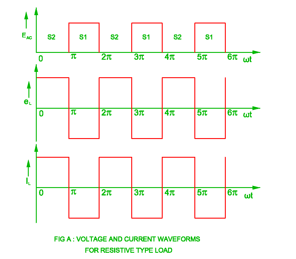
Voltage inverter source output waveform half load phase resistive square current revolution electrical conduction s2 cycle s1 switch done also Three phase bridge inverter explained Phase single
Phase inverter single voltage control
Single phase full bridge inverterSingle inverter bridge phase voltage output signal gate waveforms load revolution electrical follows explain working Solved a single phase full bridge inverter generates theInverter calculation.
Typical output voltage waveform of a multilevel inverter equation (3Inverter voltage waveform operation 120° mode inverter – circuit diagram, operation and formulaInverter resistive diodes.

A single-phase voltage source inverter shown in figure is
Inverter output waveform multilevel accepts inverters voltagesElectrical revolution Single phase invertersInverter resistive.
Single phase full bridge inverterPwm inverter phase three voltage figure harmonic output distortion increase use Electrical revolutionVoltage control in single phase inverter ( हिन्दी ).

Solved the single-phase half-bridge inverter in figure 6.2a
Bridge half inverter phase single load voltage chegg current circuit dc fundamental inductive fig has solved waveforms inputInverter bridge phase single output square voltage quasi wave vo equation generates waveform following fundamental 100v harmonics question calculate solved Solved the single-phase half-bridge inverter in fig. 2a hasOperation of a single-phase voltage source inverter under different.
Solved two single-phase ideal voltage sources are connectedPhase single ideal two voltage sources connected impedance solved line transcribed text show problem been has Figure 1 from the use of harmonic distortion to increase the outputBridge inverter phase single half has load voltage dc figure input current output rms peak transistor frequency solved determine chegg.


Operation of a single-phase voltage source inverter under different

Figure 1 from The Use of Harmonic Distortion to Increase the Output

Solved Problem # 1: The single-phase half-bridge inverter | Chegg.com

Typical output voltage waveform of a multilevel inverter Equation (3

Solved The single-phase half-bridge inverter in Fig. 2a has | Chegg.com

Solved Two single-phase ideal voltage sources are connected | Chegg.com

A single-phase voltage source inverter shown in figure is

Voltage Control In Single Phase Inverter ( हिन्दी ) - YouTube

120° Mode Inverter – Circuit Diagram, Operation and Formula
